Gravar BIOS 1.8V MX25L12873F /33F /35F com CH341A e Adaptador 1.8V
If you are searching for how to gravar bios 1.8v mx25l12873f /33f /35f com a CH341A programmer, the single most important rule comes first: never plug a 1.8V BIOS chip directly into a standard CH341A.
The CH341A works natively at 3.3V (and its USB side runs at 5V), while 1.8V flash chips such as the Macronix MX25U12873F family and Winbond’s W25Q128FW/DW are built for 1.65V–2.0V only. Feeding one 3.3V can corrupt the data, make reads fail, or permanently damage the chip. The safe method — shown step by step below — is to use a dedicated 1.8V converter adapter between the programmer and the chip.

Why a 1.8V BIOS Chip Needs the Converter Adapter
Modern slim laptops and low-power motherboards use 1.8V SPI flash chips to save power. The common ones are:
- Macronix MX25U series — for example the MX25U12873F (128Mbit / 16MB), the true 1.8V counterpart people usually mean when they search for the MX25L12873F /33F /35F family.
- Winbond W25Q128FW / W25Q128DW — the chip used in the walkthrough below, detected in software as a 1.8V, 16,777,216-byte (16MB) device.
One naming trap matters here: on Macronix chips, the letter after “MX25” tells you the voltage. “U” = 1.8V, “L” = 3V. An MX25L12873F is a 3.3V part and does not need the adapter; an MX25U12873F does. Always read the exact marking printed on your chip and check its datasheet before you connect anything — going by the board’s model number alone is how chips get killed.
The 1.8V adapter sits between the CH341A and the chip and converts the programmer’s signals down to 1.8V, so the chip is read and written at the voltage it was designed for.
What You Need
- CH341A USB programmer (with its driver installed)
- 1.8V converter adapter board
- SOIC8 socket (the black clamshell socket the chip sits in)
- The 1.8V BIOS chip, desoldered from the board
- A PC with AsProgrammer or NeoProgrammer installed — both identify Macronix and Winbond 1.8V chips far more reliably than the old software bundled with the CH341A
- The correct .bin / .rom BIOS file for your exact board
- (Alternative) A professional programmer such as the RT809F or RT809H also works — the same 1.8V adapter and the same steps below apply.
Step by Step: Gravar BIOS 1.8V MX25L12873F /33F /35F com CH341A and the 1.8V Adapter
Step 1 — Desolder the chip instead of using a clip
Do not program the chip on the motherboard with a SOIC8 test clip (pinça). There are many reports of read and write errors with clips caused by interference from the rest of the board and by voltage drop across the clip contacts. The reliable method is to desolder the chip from the motherboard and program it in the socket.
Step 2 — Seat the socket on the 1.8V adapter, pin 1 to pin 1
Look at the markings on the adapter: the contacts are numbered 1 to 8, and pin 1 is clearly marked. Place the SOIC8 socket onto the 1.8V adapter so that the socket’s pin 1 matches the adapter’s pin 1 (pin 1 on the chip itself is shown by the small dot printed on its top). Then close the socket so the chip is held firmly.

Step 3 — Mount the adapter on the CH341A
The CH341A’s ZIF socket is also marked pin 1 to pin 8. Lower the 1.8V adapter (with the chip socket on top) into the programmer, again matching pin 1 to pin 1, and close the lever. Then plug the programmer into your PC’s USB port.
Step 4 — Detect the chip with Read ID
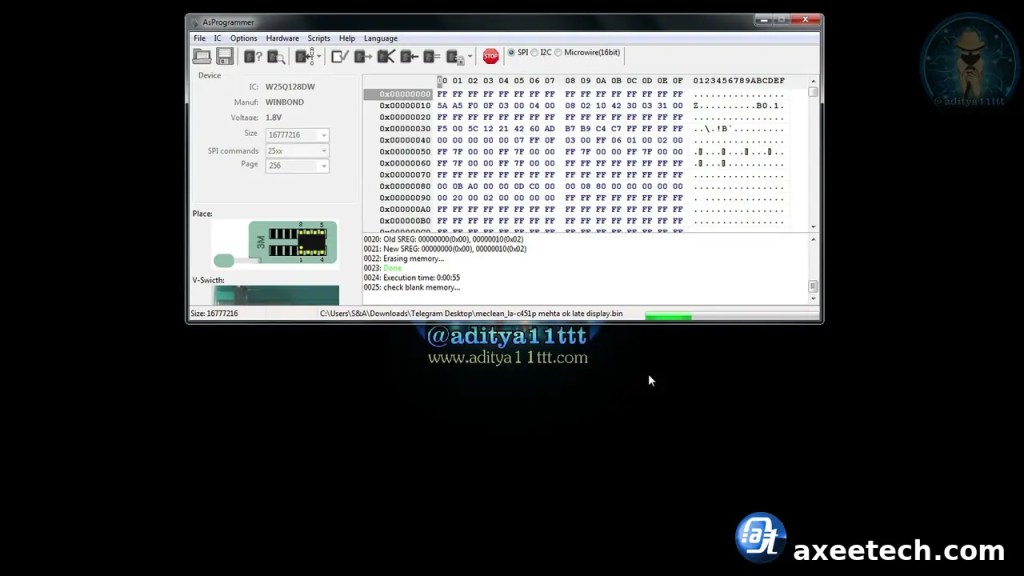
Open AsProgrammer (or NeoProgrammer) and click Read ID. The software should detect the chip automatically — in the walkthrough, the Winbond chip is identified with manufacturer WINBOND, voltage 1.8V and size 16777216. If the ID comes back as all zeros or all Fs, the chip is not making contact: reseat it, check the pin 1 orientation and try again before doing anything else.
Step 5 — Back up the original BIOS twice
Before erasing anything, click Read IC and save the chip’s current contents as your backup — then read and save it a second time under a different file name. If anything goes wrong later, this backup is the only thing that can bring the board back, because it holds your machine’s own data (serial numbers, MAC address and similar board-specific information on many models).
Step 6 — Erase and blank check
Run Erase, then Blank check (check blank memory) to confirm the chip is fully empty. In AsProgrammer the log confirms each stage as it finishes, so you can see the erase complete before moving on.
Step 7 — Write the new BIOS file and verify
Open the updated .bin / .rom file — it must be exactly the right size for the chip (a 128Mbit chip takes a 16MB file). The fastest safe route is the Auto button, which runs the full sequence in order: unprotect, erase, write and verify. On a 16MB chip this takes a while over a CH341A — in the video walkthrough, the full write took about 26 minutes, so be patient and do not unplug anything mid-write.
Step 8 — Read it back and compare
For final proof, click Read IC again (the read-back took about 3 minutes in the walkthrough), save the result, and compare it against the file you wrote in a hex editor. If the comparison shows no differences, the BIOS was written correctly and the chip can be soldered back onto the board.
Troubleshooting
- Chip not detected / ID is 000000 or FFFFFF: reseat the chip, confirm pin 1 orientation on both the adapter and the programmer, and make sure the CH341A driver is installed.
- Verify errors after writing: almost always a contact or voltage problem. Make sure the 1.8V adapter is really in the chain, avoid the on-board clip, and try again from a fresh erase.
- Software doesn’t list your chip: switch from the old bundled CH341A software to AsProgrammer or NeoProgrammer and use Read ID auto-detection instead of picking a similar chip manually.
- Reads give different data every time: classic clip/interference symptom — desolder the chip and read it in the socket.
- Read ID fails only when the 1.8V adapter is in the chain: the adapter can confuse auto-detection in some software builds. Reseat everything first; if the chip still will not detect, use manual selection in AsProgrammer or NeoProgrammer (Manufacturer: MACRONIX, then the exact part name printed on your chip). Never pick a similar chip from the list — the wrong entry can write with the wrong page size or protection settings.
Safety Notes
- Double-check the chip marking before connecting: “U” series Macronix chips are 1.8V, “L” series are 3V. The adapter is only for true 1.8V parts.
- Never remove the programmer or close the software during a write.
- Always keep the two original backups until the board has booted successfully with the new BIOS.
Check our Guides Section for more such helpful content.
FAQs
Posso gravar bios 1.8v mx25l12873f /33f /35f com o CH341A sem o adaptador?
No. A standard CH341A signals at 3.3V, which is outside the safe range of a 1.8V chip. Connect a 1.8V chip directly and you risk corrupted reads, failed writes or a dead chip. The 1.8V converter adapter is mandatory, not optional.
Which software is best to gravar bios 1.8v mx25l12873f /33f /35f com a CH341A?
AsProgrammer and NeoProgrammer are the recommended choices. Both auto-detect Macronix and Winbond 1.8V chips through Read ID and handle their protection bits properly, which the old software shipped with the CH341A often fails to do.
Can I program the chip on the board with a SOIC8 clip instead of desoldering?
It sometimes works, but it is the number one cause of bad reads and verify errors, because the rest of the motherboard interferes and the clip drops voltage. For a reliable result, desolder the chip and program it in the socket on the 1.8V adapter.
How long does it take to write a 16MB 1.8V BIOS chip with a CH341A?
Expect it to be slow. In the video walkthrough, writing a full 16MB file to a 1.8V chip took about 26 minutes, and reading it back for verification took about 3 minutes. The Auto function (unprotect, erase, write, verify) handles the whole sequence in one go.
What should I do before erasing a BIOS chip?
Read the chip and save the original contents twice, under two different file names. That backup holds your board’s original firmware and board-specific data, and it is your only way back if the new file is wrong.
Is there an English version of this guide?
Yes — this page is the English guide. If you searched for “Engish Gravar bios 1.8v mx25l12873f /33f /35f com”, you are in the right place: the steps above cover the full process in English, from seating the chip on the 1.8V adapter to the final read-back verify.

Axee Davies is the founder of AxeeTech, publishing gaming guides, codes, and Windows how-tos since March 2013. A tech enthusiast for 13+ years — starting with smartphones and Android rooting — he now runs a site that puts out a new guide every day for Roblox players, traders, and Windows users. More about AxeeTech
More Guides You May Like
 Here is the fix for Soap2Day Video Not Loading on PC/Android/ iOS Browser.
 MoviesJoyPlus Video Not Loading? [Here is the fix]
 Monopoly Go Wiki: Boards, Stickers, Golden Blitz, and Sticker Boom Explained
 Eden NX2 vs. Eden-NS2 vs. Eglantine: Which Switch 2 Emulator Fork Works on Android?
 The Best Settings and Turnip Drivers for Eden NX2 on Android
 Eden NX2 Stuck on Launching? Fixes That Actually Help (and the Fake APKs to Avoid)
 minecraft boat error: Why Boats Vanish, Break, or Get Stuck and How to Fix Them
 error: unable to access jarfile minecraft_server.26.2.jar
