field coating specification 1167 series and procedure mp/0/a/1000/006
If you have been handed a coating scope that cites the field coating specification 1167 series and procedure mp/0/a/1000/006, you are looking at a project-controlled field joint coating package: the 1167 series specification sets the requirements, and procedure mp/0/a/1000/006 is the working method statement that tells the coating crew exactly how to meet them, joint by joint, on a pipeline right-of-way. This guide explains what the package governs, how it is normally structured, and the standard execution and inspection workflow used under specifications of this kind.
One important note before the detail: the specification and procedure documents themselves are project-issued and controlled. The acceptance values that govern a real job — dry film thickness, holiday test voltage, peel strength — are the ones written in the issued revision of those documents, and they always override any typical value quoted in a guide like this one. What follows is the standard industry workflow that procedures of this type codify, referenced against the international standards they normally invoke.
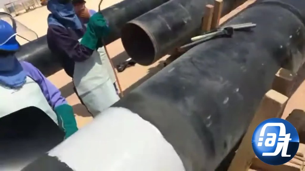
What the 1167 Series Field Coating Specification Covers
A field coating specification exists because a pipeline’s factory-applied coating has to stop short of every weld. The bare steel left at each girth weld — the cut-back area — is the most corrosion-vulnerable part of the line, and it can only be protected after welding, out in the field. The 1167 series specification therefore covers the coating of field girth welds on buried or above-ground pipelines: the coating systems permitted, the materials that may be used, the surface preparation standard, the application method, and the inspection and testing that proves each joint is sound before it is buried or backfilled.
The coating systems typically permitted under a specification of this type are the three field joint workhorses: fusion-bonded epoxy (FBE) powder applied to a heated joint, heat-shrinkable wraparound sleeves over a solvent-free epoxy primer, and liquid-applied epoxy systems for repairs and complex shapes. Which system applies to a given joint is fixed by the project coating schedule, not by crew preference.
How Procedure MP/0/A/1000/006 Is Structured
Procedure mp/0/a/1000/006 is the execution document written against the specification. A procedure of this kind is normally organised into the same sections on every project, because auditors, inspectors and coating crews all need to find the same information in the same place:
- Scope and references — the joints covered, and the standards invoked (typically ISO 8501-1 for surface cleanliness, ISO 8502-9 for soluble salts, ISO 21809-3 for field joint coatings, and the coating manufacturer’s instructions).
- Materials — approved coating products, batch control, storage conditions and shelf-life rules.
- Personnel qualification — the coating applicators and inspectors must be qualified and their qualifications recorded before work starts.
- Execution steps — surface preparation, preheating, primer and coating application, in sequence.
- Inspection and testing — what is checked on every joint, and what is sampled periodically.
- Repairs — how defects are fixed and re-tested.
- Records — the joint log that traces every weld to its materials, crew, conditions and test results.
Surface Preparation: The Step That Decides Everything
Most field joint coating failures trace back to surface preparation, not to the coating material. Under a specification of this type, the bare steel at the joint is abrasive-blast cleaned to near-white metal, Sa 2½ under ISO 8501-1 (the SSPC-SP 10 equivalent), with the edges of the existing factory coating feathered back — typically around 50 mm — so the new coating overlaps sound material rather than a sharp step.
The checks that normally accompany preparation are: a surface profile in the 50 to 100 micrometre range, residual soluble salts (chlorides) not exceeding 40 mg/m² measured per ISO 8502-9, and a dust assessment rating no worse than class 2 under ISO 8502-3. The first blasted joint of each shift is normally the one tested for chlorides. If any of these checks fail, the joint is re-blasted before coating starts — coating over a failed surface is never accepted.
Application Procedure: From Preheat to Finished Joint
For the heat-shrink sleeve system — the most common field joint system on buried onshore pipelines — the application sequence under a procedure like mp/0/a/1000/006 runs as follows:
- Preheat. The joint area is heated to the temperature window specified by the sleeve manufacturer, and the steel temperature is verified with a contact thermometer or infrared gauge.
- Epoxy primer. A solvent-free epoxy primer is applied to the prepared steel and the feathered factory coating, at the manufacturer’s specified thickness, immediately after preparation so flash rust cannot form.
- Sleeve installation. The radiation cross-linked polyolefin sleeve, with its thermoplastic adhesive layer, is wrapped around the joint with the specified overlap onto the factory coating on both sides.
- Shrinking. Heat is applied evenly — usually working from the centre of the sleeve outwards — until the sleeve has fully shrunk onto the pipe and adhesive flow is visible at both edges.
- Closure. The closure patch is applied over the sleeve overlap and shrunk down, completing the joint.
Environmental limits apply throughout: coating stops when the steel temperature is within 3 °C of the dew point, when wind carries dust onto the prepared surface, or when rain threatens the open joint. These hold points are written into the procedure because a joint coated in bad conditions fails early, however good the material is.
Check more helpful articles in our Guides Category.
Inspection and Testing of Every Joint
Inspection under a field coating procedure is not a sample — it is a per-joint discipline, with destructive tests sampled periodically:
- Visual examination of every joint: full shrinkage, no bridging, no damage, adhesive flow at the edges.
- Thickness checks on the coating body and on the weld area, with a magnetic or ultrasonic gauge.
- Holiday detection on every joint with a full-circle high-voltage detector — typically 15 kV or 25 kV DC depending on the coating system, and only once the surface temperature is below the detector limit (commonly 50 °C for sleeve systems, 80 °C for FBE).
- Peel testing sampled at a set frequency — commonly one joint in every 50, or one per day’s production — to prove adhesion to both the steel and the factory coating.
- Adhesion testing on FBE joints, typically by the X-cut method per ASTM D6677.
Any holiday found is marked, repaired with the approved repair material, and re-tested. A joint with an unrepaired holiday is not backfilled, and a joint that fails a peel test triggers re-testing of the surrounding joints — the procedure defines the escalation, and the inspector enforces it.
Repairs, Records and Traceability
Repairs use only the coating manufacturer’s approved repair material, applied exactly as the manufacturer directs, and every repair is holiday-tested again after curing. The joint log is the document that makes the whole system auditable: for each weld it records the joint number, pipe heat number, coating batch numbers, primer batch numbers, crew, ambient and steel temperatures, humidity, dew point, inspection results and any repairs. When a pipeline operator asks, years later, what protected a particular weld, the joint log is the answer.
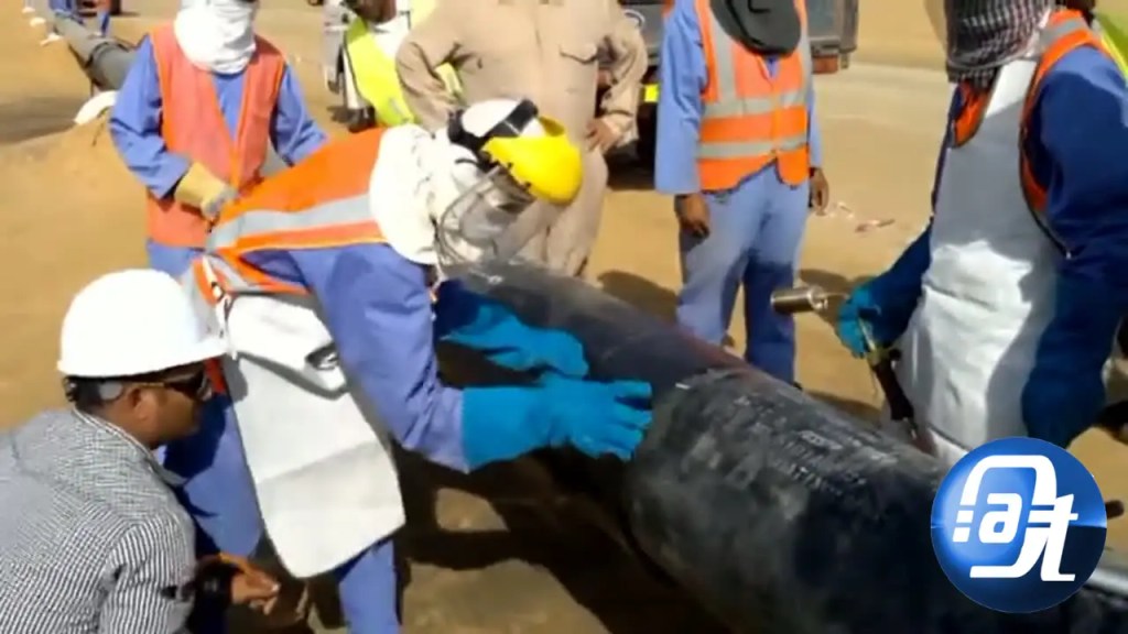
Frequently Asked Questions
What is the field coating specification 1167 series and procedure mp/0/a/1000/006?
It is a project field joint coating package: the 1167 series specification sets the requirements for coating pipeline field girth welds, and procedure mp/0/a/1000/006 is the step-by-step method statement the coating crew follows to meet those requirements on site.
Which coating systems does a specification like this cover?
Typically fusion-bonded epoxy (FBE), heat-shrinkable sleeves over epoxy primer, and liquid epoxy systems for repairs. The coating schedule for the specific project states which system applies to each joint.
What surface preparation does the field coating specification 1167 series require?
As with most pipeline specifications of this type, abrasive blasting to Sa 2½ near-white metal, a 50 to 100 micrometre profile, chlorides at or below 40 mg/m², and feathering of the factory coating edge — with the exact values confirmed against the issued revision of the specification.
How is a finished field joint tested?
Every joint gets a visual examination, thickness checks and a full-circle holiday test. Peel and adhesion tests are sampled periodically, typically one joint in 50 or one per day’s production. Any defect found is repaired and re-tested before backfill.
Where do I find the exact acceptance values for procedure mp/0/a/1000/006?
In the issued, revision-controlled copy of the procedure held by the project — its tables for thickness, test voltage and peel strength override any typical value quoted in guides or manufacturer literature. If the revision you hold is not the current one, request it from document control before starting work.
Sources
- ISO 21809-3 — Petroleum and natural gas industries, external coatings for buried or submerged pipelines, field joint coatings.
- ISO 8501-1 — Preparation of steel substrates, visual assessment of surface cleanliness (Sa 2½).
- ISO 8502-9 — Field method for the conductometric determination of water-soluble salts.
- AMPP/NACE SP0188 — Holiday testing of new pipeline coatings.
- Pipeline Field Joint Coating — The Piping Engineering World

Axee Davies is the founder of AxeeTech, publishing gaming guides, codes, and Windows how-tos since March 2013. A tech enthusiast for 13+ years — starting with smartphones and Android rooting — he now runs a site that puts out a new guide every day for Roblox players, traders, and Windows users. More about AxeeTech
More Guides You May Like
 Do you know Aerna, the largest Minecraft Map Project, covers over 5,200 km square?
 Dyson DP04 Error Display: Warning Triangle, Filter Alerts and Fixes
 Error Code: 0x89245111 Code: Swamp in Minecraft Launcher — Causes and Fixes
 Gravar BIOS 1.8V MX25L12873F /33F /35F com CH341A e Adaptador 1.8V
 What Is the Blue Dot Beside the Battery in Samsung Phones After the One UI 9 Update?
 ArtCraft Review: 12 Free Adobe & Microsoft Office Alternatives (Launcher + Download Guide)
 Star Citizen Retribution: What It Is and Can You Buy It
 Star Citizen Ranta Dung: Where to Find It and Price
